

matthewn2002
New member
- Joined
- Aug 9, 2025
- Messages
- 1
Hi everyone,
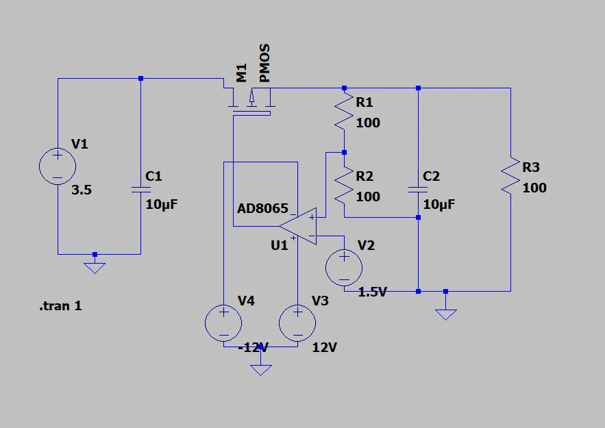
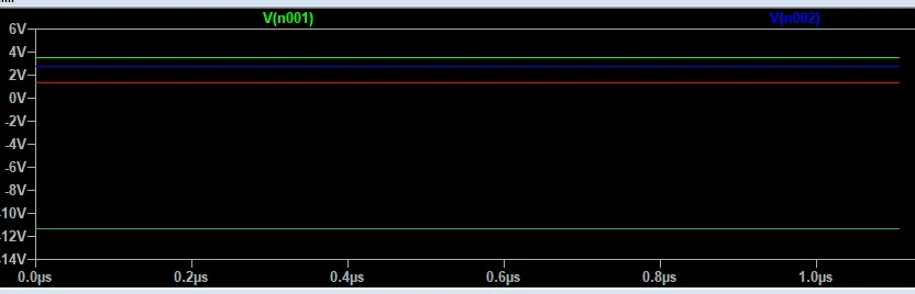
I'm an ee student trying to study power electronics on my own. I'm designing a basic LDO to solidify my understanding, but something is wrong and I'm not sure what. Below is my circuit and simulation, if anyone has any feedback, I'd much appreciate it!
Node 1 (Green) - Input Voltage
Node 2 (Blue) - Output Voltage
Node 3 (Red) - Voltage on the non inverting side of op amp
Node 4 (Cyan) - Output of op amp
I'm an ee student trying to study power electronics on my own. I'm designing a basic LDO to solidify my understanding, but something is wrong and I'm not sure what. Below is my circuit and simulation, if anyone has any feedback, I'd much appreciate it!
Node 1 (Green) - Input Voltage
Node 2 (Blue) - Output Voltage
Node 3 (Red) - Voltage on the non inverting side of op amp
Node 4 (Cyan) - Output of op amp

