
Hey everyone,
I'm trying to design an application using two ATmega32 microcontrollers. The first reads a sensor (in my case, atmospheric pressure) and sends the measured value to the second via serial interface. The second microcontroller receives the value and displays it on an LCD or 7-segment LED display. and my system must:
– read and process the sensor signal to obtain the physical quantity
– display the measured value
– transmit the value via serial interface
– trigger a warning if the value is below or above a chosen threshold, by lighting up LEDs and showing an error message .
My problem is with the block diagram. I'm not sure how to properly organize the power input, sensor, data processing, display, and alert parts in a clear and logical way.
I've looked at a few examples, but they all seem either too simple or too complex for what I need. Could anyone share an example or give me some advice on how to structure a proper block diagram for this kind of system?
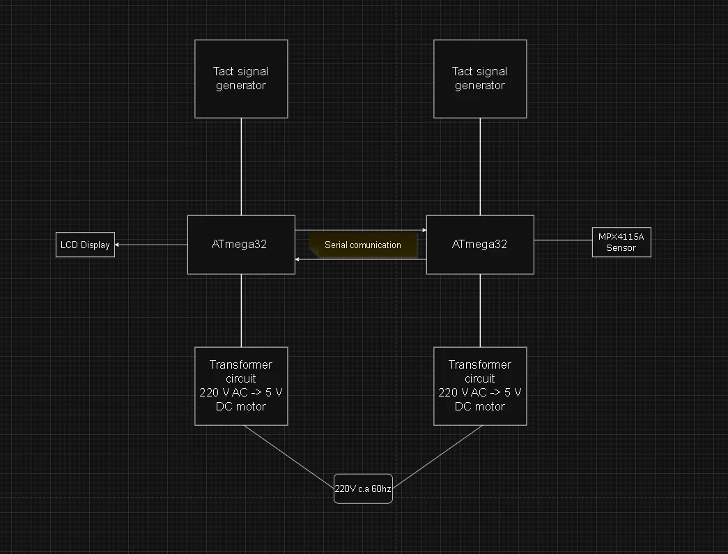
(i ll leave a little diagram with something I tried)
Thanks in advance!
I'm trying to design an application using two ATmega32 microcontrollers. The first reads a sensor (in my case, atmospheric pressure) and sends the measured value to the second via serial interface. The second microcontroller receives the value and displays it on an LCD or 7-segment LED display. and my system must:
– read and process the sensor signal to obtain the physical quantity
– display the measured value
– transmit the value via serial interface
– trigger a warning if the value is below or above a chosen threshold, by lighting up LEDs and showing an error message .
My problem is with the block diagram. I'm not sure how to properly organize the power input, sensor, data processing, display, and alert parts in a clear and logical way.
I've looked at a few examples, but they all seem either too simple or too complex for what I need. Could anyone share an example or give me some advice on how to structure a proper block diagram for this kind of system?
(i ll leave a little diagram with something I tried)
Thanks in advance!